Osteora
Choosing Posterior Pedicle Screw Systems is not a matter of selecting the most feature-rich tray. The decision shapes how a surgeon achieves fixation, alignment, and stability for a specific patient. A system that works well in one case may not suit another. Anatomy matters. So does the surgical plan.
Spine surgeon Dr. Alexander R. Vaccaro is a relevant authority in spinal care. As a paraphrase of a patient-centered principle reflected in his clinical work: “Match the fixation strategy to the patient’s anatomy and the goals of surgery, not to habit alone.” That is a useful starting point, not a substitute for clinical judgment. Surgeons should assess imaging, bone quality, intended screw trajectories, and the system’s compatibility with rods and instruments. A few millimeters can matter near a nerve or vessel. Small details count.
This guide outlines practical questions for evaluating screw design, material, instrumentation, and procedural needs. It also considers training, available evidence, and the manufacturer’s support for the system. These factors deserve scrutiny, but no checklist can remove every uncertainty. Some choices remain difficult. The best option depends on the patient, the surgeon’s experience, and the procedure’s objectives. This introduction is informational, not a recommendation for any individual patient.
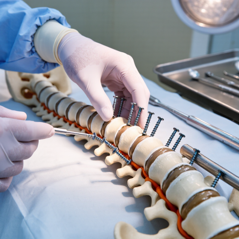
Posterior pedicle screw systems are assemblies used by trained spine surgeons to stabilize selected spinal segments. Understanding each component helps explain how the construct is planned and assessed. A pedicle screw passes through the vertebral pedicle into the vertebral body. Its dimensions and path must suit the patient’s anatomy. Small details matter.
The screw head, often called a tulip, receives a connecting rod. Polyaxial heads can pivot to help the rod fit across screws placed at different angles. A locking cap secures the rod inside the head. Some systems also include cross-connectors, which link rods across the spine when clinically appropriate. Instruments for placement and tightening are part of the system, too. Compatibility matters: parts that look similar may not work together.
System selection depends on the spinal level, the planned procedure, bone quality, and the surgeon’s technique. Imaging helps assess anatomy, but it does not replace clinical judgment. The hardware list is tidy; real anatomy is not. That gap deserves careful thought. Patients can ask their surgeon which components are planned and why, while leaving device selection to the treating team. The exact plan varies.
Posterior pedicle screw planning begins with the patient, not the implant. Review thin-slice CT images for pedicle width, cortical integrity, and the safest screw trajectory at each level. A narrow thoracic pedicle may require a different diameter or entry angle than a broad lumbar pedicle. Check bone quality, prior surgery, deformity, and any congenital variation. MRI and clinical examination add context, especially when nerve compression or weakness affects the operative plan. Small details matter.
Clinical goals shape construct choice. Is the aim to stabilize a fracture, treat degenerative instability, or correct deformity? Each may require different fixation levels and alignment targets. In a 2013 Spine study, Schwab and colleagues found that pelvic incidence–lumbar lordosis mismatch above 11 degrees, pelvic tilt above 22 degrees, and sagittal vertical axis above 47 mm were associated with greater disability in adult spinal deformity. These measures inform planning; they do not prescribe a screw system. Account for osteoporosis and the patient’s ability to tolerate surgery, too. Imaging can still leave uncertainty.
Tips: Compare planned screw dimensions with measured pedicle anatomy on CT. Confirm levels and trajectory in more than one plane. Discuss bone quality, neurologic findings, and alignment goals with the surgical team before selecting a system.
Posterior pedicle screw systems should be compared as complete constructs, not as isolated screws. Thread shape, pitch, diameter, and length affect purchase and insertion feel. A surgeon considers bone quality, vertebral anatomy, and the planned trajectory when reviewing these features. Polyaxial heads allow more rod-alignment flexibility, while fixed-angle heads can offer firmer control. Neither option fits every case. Small differences matter.
Materials influence handling and construct behavior. Titanium alloys are widely used and may create less imaging artifact than stainless steel, though geometry and scan settings also matter. Stainless steel can be stiffer, but material alone does not determine stability. Check component compatibility: mixing parts can affect fit and performance. That detail is easy to overlook.
Construct options include rod diameter, rod contour, screw-head interface, connectors, and the number of fixation points. Compare whether a system supports the planned alignment and provides a secure connection without unnecessary complexity. Surgeons also weigh bone quality, imaging, revision needs, and operative technique. It is easy to overvalue a technically impressive feature that adds little in a specific case. Selection should follow the surgeon’s assessment, imaging, and current device instructions.
| Decision Area | Common Options | Typical Characteristics | Construct Considerations | Selection Points |
|---|---|---|---|---|
| Screw-head articulation | Polyaxial or monoaxial | Polyaxial heads allow the screw head to angulate relative to the shaft, helping accommodate rod placement. Monoaxial screws have a fixed head-to-shaft relationship and can provide a more direct reduction point. | Either type may be used in a rod-based posterior construct. The choice can affect rod seating, alignment, and reduction technique. | Consider anatomy, desired alignment, reduction needs, and the surgeon’s preferred technique. |
| Screw shaft and thread | Solid or cannulated; varied diameters, lengths, and thread profiles | Solid screws are not cannulated. Cannulated screws have a central channel that can facilitate placement over a guidewire. Dimensions and thread geometry vary among systems. | Implant dimensions must match the intended anatomy and the system’s compatible instruments and components. | Assess patient anatomy and bone quality using appropriate imaging and clinical judgment; do not assume dimensions are interchangeable across systems. |
| Trajectory and screw path | Traditional pedicle trajectory or cortical bone trajectory | Traditional screws pass through the pedicle toward the vertebral body. Cortical bone trajectory screws follow a different, more medially starting and cranially directed path intended to engage cortical bone. | Trajectory affects screw position, compatible connectors, and the geometry of the posterior rod construct. | Choose a technique appropriate to the anatomy, pathology, imaging, and planned fixation levels. |
| Augmentation features | Standard screws or fenestrated screws for cement augmentation when indicated | Fenestrated designs have openings in the shaft through which compatible bone cement may be delivered. Cement use introduces additional procedural and safety considerations. | Use only with compatible components and instruments, and follow the system’s instructions for use and applicable cement guidance. | Evaluate bone quality, indications, contraindications, and risks; augmentation is not appropriate for every patient or procedure. |
| Screw material | Commonly titanium alloy; some systems may use other implant alloys | Titanium alloys are widely used for spinal fixation implants. Material composition and surface characteristics are specific to the implant and should be verified in its technical documentation. | Confirm that screws, rods, and connectors are approved for use together within the selected system. | Review material compatibility, patient sensitivities, and MRI conditions in the device labeling. Do not infer MRI status from material alone. |
| Rod material and profile | Titanium alloy, cobalt-chromium alloy, or other system-specific options; commonly round rods | Rod materials differ in mechanical properties. Rod diameter, contourability, and material availability depend on the system; rods are not universally interchangeable. | Rod material and diameter should be compatible with the screw heads, set screws, and connectors used in the construct. | Consider the intended construct, contouring requirements, and the manufacturer’s compatibility specifications. |
| Construct configuration | Short- or long-segment fixation; bilateral or selected unilateral fixation; connectors or cross-links where appropriate | Construct length and component arrangement depend on the clinical indication, anatomy, and operative plan. Cross-links connect bilateral rods when included in a compatible system. | Additional options may include rod connectors, transition components, or pelvic fixation components, depending on the planned levels and system. | Plan the complete construct, including all required compatible components, rather than selecting screws in isolation. |
| Reduction and alignment options | Standard screw heads or reduction-style screws with extended tabs | Reduction-style screws provide additional head height or engagement features that can help draw a rod toward the screw head during reduction. They may require specific instruments and technique. | Confirm that reduction screws and their instruments are compatible with the selected rod and screw-head design. | Use when consistent with the surgical plan; account for access, soft-tissue clearance, and the system’s reduction technique. |
| System compatibility and documentation | One validated, compatible system configuration | Screw heads, rods, set screws, connectors, and instruments are designed to work in defined combinations. Similar-looking components from different systems may not be compatible. | Verify component sizes, material combinations, instrument requirements, and approved configurations in current device documentation. | Base final selection on the specific device labeling, applicable standards, patient factors, and qualified clinical judgment. |
Note: These are general design considerations, not a ranking of specific devices. Features may be combined in a single system, and availability varies. Always consult current device documentation and use clinical judgment.
How to Choose Posterior Pedicle Screw Systems
Assess Surgical Compatibility and Imaging Considerations
A suitable posterior pedicle screw system should match the planned anatomy, surgical approach, and imaging workflow. Check available screw diameters and lengths against preoperative CT measurements, especially where pedicles are narrow or rotated. Confirm that screw heads, tulip designs, and rods work together within the same system. Small details matter. A connection mismatch can complicate assembly when access is limited.
Imaging affects both planning and placement. A 2012 systematic review in the European Spine Journal reported pedicle screw accuracy ranges of 69–94% for freehand techniques and 89–100% for navigation-assisted techniques. The wide ranges reflect differences in studies and methods; navigation does not remove the need for sound anatomical judgment. Consider whether the system suits the facility’s fluoroscopy or navigation equipment, and review implant labeling for MRI conditions and artifact information. Metal can obscure nearby anatomy. Discuss image quality and implant-specific conditions with the radiology team rather than assuming all systems behave alike.
Tips: Before surgery, verify instrument availability, compatible connectors, and imaging settings. Review CT slices in multiple planes. If a measurement or image is unclear, pause and reassess; small uncertainties can matter.
Qualitative ratings show the general usefulness of each modality for common planning and assessment tasks; they are not measured clinical outcomes. CT is useful for assessing bony anatomy and screw position, fluoroscopy supports intraoperative guidance, and MRI is useful for soft-tissue evaluation. Metal-related artifact varies by implant material, design, and imaging protocol. Confirm system component compatibility, device labeling, and local imaging protocols before use.
Choosing a posterior pedicle screw system requires more than comparing catalogs. Review evidence for the intended spinal levels, bone quality, and surgical approach. Check whether studies report screw loosening, breakage, revision, and patient outcomes—not just placement accuracy. Small studies can look reassuring while missing uncommon complications. That matters.
FDA 510(k) clearance generally establishes substantial equivalence to a legally marketed device; it does not prove clinical superiority. FDA’s MAUDE database contains millions of medical-device reports, but reports are not verified event rates and cannot establish causation. Use them as safety signals, then compare findings with peer-reviewed studies and device labeling. A spreadsheet tracking study size, follow-up, and reported complications can expose gaps quickly.
Safety review should include the risk-management process under ISO 14971:2019 and relevant biocompatibility evidence under ISO 10993-1. ASTM F1717 offers standardized bench testing of spinal implant constructs, but laboratory strength is not a substitute for clinical outcomes. Ask for test conditions and failure modes; a number without context can mislead. Regulatory status also varies by market, so verify current local requirements and instructions for use. Evidence is rarely perfect. Note uncertainty rather than treating missing data as proof of safety.
It is an assembly used by trained spine surgeons to stabilize selected spinal segments. Screws pass through the vertebral pedicles into the vertebral bodies. Small details matter.
It may include screws, pivoting heads, connecting rods, locking caps, and cross-connectors. Placement and tightening instruments are also needed. Parts that look alike may not fit together.
Surgeons compare screw diameter and length with the patient’s anatomy, often using thin-slice CT images. Pedicle width and trajectory can differ between spinal levels. Anatomy is not always tidy.
The spinal level, planned procedure, bone quality, prior surgery, and surgical approach all matter. Stabilizing a fracture may require different planning than correcting a deformity. The exact plan varies.
CT helps assess pedicle size and bone structure. MRI and clinical examination provide additional context, including nerve compression or weakness. Images can still leave uncertainty.
No. A 2012 review reported accuracy ranges of 69–94% for freehand methods and 89–100% for navigation-assisted methods. Study methods differed, and navigation does not replace anatomical judgment.
Screw heads, rods, locking caps, and connectors must work together. A mismatch can complicate assembly, especially when surgical access is limited. Check the instruments, too.
Ask which components are planned and why they suit the clinical goals. Patients can also ask about bone quality and imaging considerations. The treating team selects the system.
Choosing Posterior Pedicle Screw Systems requires balancing the needs of the patient with the demands of the planned spinal procedure. Begin by understanding the system’s components and evaluating the patient’s anatomy, diagnosis, bone quality, and clinical goals. These factors help determine suitable screw dimensions, placement strategies, and construct configurations while supporting individualized surgical planning.
Compare design and material characteristics, and consider how the system fits the surgeon’s preferred techniques and available instruments. Imaging requirements should also be reviewed to support accurate planning and intraoperative assessment. Finally, examine relevant clinical evidence, safety information, and applicable regulatory standards. A careful, structured evaluation can help clinicians select a system that is appropriate for the patient and compatible with the intended procedure.